Issue 047, Nov 15, 2022
Grant Justice, Sr. Research Metallurgist
Welding of arcing contacts presents a major reliability concern in any application where the contacts are opened or closed under power, and several material and mechanical mitigation strategies have been developed over time to combat it.
Welding of contacts primarily occurs due to electrical arcs. As the two metal contacts approach each other, the strength of the electric field between the contacts will increase and, if sufficient voltage is present in the circuit, an electrical arc will occur.¹ This arc will exist until the contacts finish closing and direct metal-to-metal contact is achieved. One of the major consequences of this arc is localized heating and melting of the contact surface that is then pressed against the other contact, occasionally resulting in a weld between the contacts as seen in Figure 1. Several other conditions can cause transient arcing and welding of the contacts. One example is the mechanical bounce that can occur when the contacts close causing them to briefly reopen, this can generate an opening arc that will also lead to localized melting and welding of the contacts. Welding of contacts can also occur if a high contact resistance develops causing sufficient localized heating to melt the contact materials. Once welded closed, the contacts are more difficult to separate, potentially resulting in a failure of the switch.
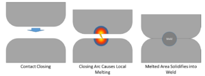
Figure 1: Closing arc formation and contact welding.
In anticipation of contact welding during close and other events, the force required to break the weld may be predicted and factored into the design of the switch. The weld force is dependent on a constant determined by the material and the energy put into the weld. This relationship generally takes the form of Equation 1.²
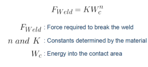
Equation 2
This equation clearly identifies two design strategies to reduce the force necessary to break the weld: either use a material that is more resistant to welding, or reduce the energy dissipated into the contact area.
Most contact materials tend to be silver-based, due to silver’s high electrical conductivity and resistance to oxidation. Second phases are added to the silver in the contacts in order to increase the resistance to welding and/or to lower the strength of the weld. These can be the additions of metals insoluble in a silver matrix, such as nickel or tungsten; ceramics, like cadmium oxide or tin oxide; or graphite. In addition to increasing the resistance to welding, these composite materials tend to be more expensive,
difficult to fabricate, and have higher contact resistance when closed. Examples of some common contact materials can be found in Figure 2.
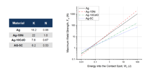
Figure 2: Weld force vs energy relationships for some arcing contact materials.²
Mechanical design can heavily influence the weld force by reducing the energy discharged into the contact spot. Design changes such as increasing the closing speed-thereby reducing the arcing time-or taking steps to reduce contact bounce can greatly reduce the total arcing time and therefore reduce the total energy discharged by the arc into the contact. Welded contacts are also more easily separated by sharp impacts compared to smoothly applied separating force, so designing a mechanical action of
opening that includes an impact can greatly enhance the ability to separate a high force weld.
Deringer-Ney has decades of experience in the fabrication and assembly of electrical contacts using silver, silver alloys, silver metal oxides, and silver – refractory metal composites to suit a wide range of applications.
Paliney® and Neyoro™ are registered trademarks of Deringer-Ney Inc.
References:
- D. Montone, Tech Brief 006 – Arcing Phenomenon in Make-Break Contacts, 2021. https://deringerney.com/arcing-phenomenon-in-make-break-contacts/
- Slade, P. “The Consequences of Arcing” Electrical Contacts: Principles and Applications, edited by Slade, Paul G. CRC press, 2017.pp. 654-657