Issue 040, July 20, 2022
Megan K. Puglia, Ph.D., Sr. Research Metallurgist
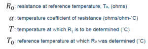
Material resistance depends on a material’s innate resistivity as well as a component’s length and cross-sectional area. Resistivity, and therefore resistance, also changes as a material is heated or cooled. The temperature coefficient of resistance, or TCR, (α) is the factor of change in resistance introduced into a material as the temperature of the material is changed by 1 degree. It takes into account both increases in resistivity and length of the conductor that results from thermal expansion. Conducting materials’ resistances increase as their temperature increases, resulting in a positive coefficient of resistance (α > 0). Material resistance values are commonly reported at 20˚C (room temperature). Temperature variations within a few degrees do not drastically change a material’s resistance but larger temperature changes result in a significant difference. Using a material’s temperature coefficient of resistance value allows for the estimation of material’s resistance (RT) (ohms) at a specific temperature (Equation 1).¹
![]()
In Equation 1,
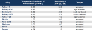
In Table 1 the temperature coefficients of resistance are listed for a collection of Deringer-Ney, Inc. (DNI) alloys and pure elements. DNI generally considers the TCR to be a temper-independent material property.
For metallic components, an increase in temperature causes free electrons to be more frequently scattered. More frequent scattering, decreases the mean free path of an electron and results in increased resistance. Generally pure elements have the fewest scattering sites and therefore lower resistivity compared to alloys where alloying additions increase the lattice imperfections and overall scattering sites. However, pure elements tend to have higher temperature coefficients of resistance. Figure 1 plots resistance values versus temperature for a number of DNI alloys and pure elements where the slope of each line is proportional to the TCR.
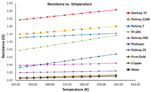
Figure 1: Resistance versus temperature for a collection of pure elements and DNI alloys. Resistance values were calculated using each materials’ TCR for a 200 μm diameter wire with a 10 cm length.
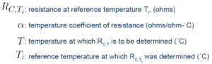
In the design of electrical contacts it is important for bulk resistance of the contact and constriction resistance (RC) to be low in order to maintain high electrical conductivity. Constriction resistance occurs when increased resistance at an a-spot causes increased Joule heating, and therefore a temperature increase at said spot. The change in RC due to joule heating temperature changes can be calculated using Equation 2, where α remains the temperature coefficient of resistance for the material.¹
![]()
In Equation 2,
Constriction resistance is dependent on material hardness, as softer materials have increased real contact areas under the same applied loads. Due to this, Equation 2 is only valid at temperatures below the softening temperature of the material. Joule-heating that causes material softening will result in a decrease in constriction resistance.¹
DNI designs alloys and electrical contacts with years of experience in the nuances of resistivity, temper and temperature coefficients of resistance and can help choose the best material for specific applications and temperatures.
Table 1: Temperature Coefficient of Resistance and Resistivities for Pure Metals and Alloys at Specific Tempers. 1,2,3
References:
- Pitney KE. Hardness. In: Ney Contact Manual, Revised 1st Ed: Properties of Materials. Bloomfield, Connecticut: The J.M. Ney Company; 2022. p. 62-68.
- Haynes, William M., et al. “Properties of Solids.” CRC Handbook of Chemistry and Physics: A Ready-Reference Book of Chemical and Physical Data: 2012-2013, CRC Press, Boca Raton, FL, 2012, pp. 12–41-12–42. 5.
- Brandes, Eric A., and Colin James Smithells. Smithells Metals Reference Book. 6th ed., Butterworths, 1983.