Issue 010, May 13, 2021
Patrick K. Bowen, Ph.D., R&D Manager
Microhardness testing is a mainstay technique in the mechanical characterization of fine wires and thin strip products. The technique is able to test small sample volumes, and serves as a meaningful indicator of wear in low energy sliding contact systems.
Measurement utilizes a diamond indenter of fixed geometry that is pressed into a polished, planar surface under constant load. After a prescribed dwell time, the load is removed, and the impression is measured using an optical microscope. A higher microhardness may be interpreted as greater resistance to plastic deformation; the diamond indenter thus leaves a smaller observable impression on harder, stronger materials.[1]
Two indenter geometries are prevalent in microhardness testing of noble metals and alloys:
- the Vickers (alternatively “diamond pyramid hardness”) indenter is a square-base pyramid that leaves a neat, 1:1 aspect ratio indentation; and
- the Knoop indenter is also a pyramid, but is elongated in one axis to create a narrow, rhombus-shaped impression.
Larger hardness impressions are more easily and repeatably measured. Therefore, the highest reasonable load for a given material dimension is preferred. For very fine or thin materials, low-load microhardness measurements of 100, 50, or 25 gf are utilized. A benefit of the Knoop geometry is a greater material displacement in one direction, which can be aligned with the longitudinal direction of a narrow sample. The Knoop indent is measured along its major axis. Knoop therefore presents a larger feature for length measurement than a comparable Vickers indent.
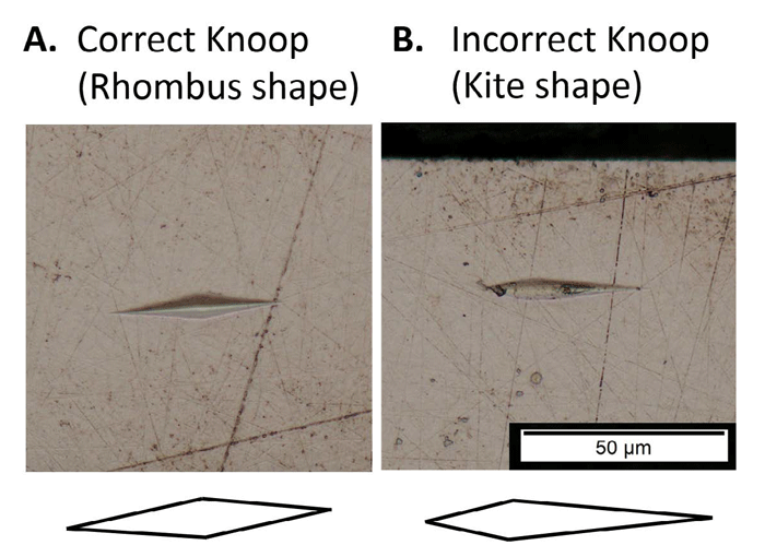
Figure 1. Comparison of Knoop indents appearing as a normal rhombus (A) and abnormal kite (B) shapes.
However, reliance on measurement of one axis and axial asymmetry of the indenter also makes the Knoop scale sensitive to alignment error. Misalignment will manifest as quadrilateral indents in the shape of a kite, rather than a rhombus, as illustrated in Figure 1. Systematic machine misalignment can be a source of discrepant hardnesses between two testers or parties, while less repeatable sources of misorientation can result in random error in the measurement.
Consider the Knoop indenter illustrated in Figure 2. The standard Knoop indenter has a half angle of the indenter (α/2) along its major axis of 86.25° [2]. In other words, the major pyramidal axis of a vertically aligned Knoop indenter (θ = 0 in Figure 2) will engage a specimen at an angle of only 3.75°.
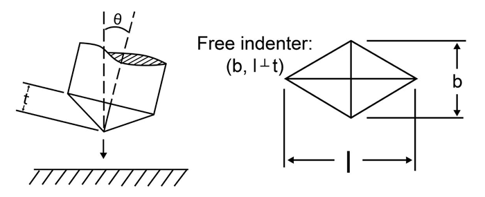
Figure 2. Knoop indenter geometry illustrating the indenter depth (t), pyramid major axis (l), and pyramid minor axis (b), as well as possible misalignment (θ).
In the case where a kite-shaped Knoop indent is observed, the degree of misalignment may be calculated. Using observable values from Figure 1 and knowledge of the Knoop indenter geometry, we may construct the following relationships, illustrated in Figure 3:
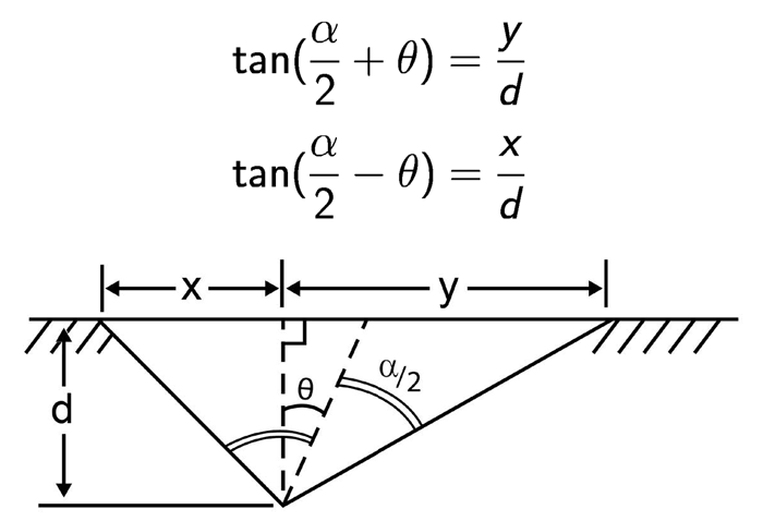
Figure 3. Cross-section of an asymmetric, kite-shaped Knoop indent along its major axis. A term for depth of the indentation (d) is introduced here.
Solving the latter equation for d, substituting into the former, then solving for the ratio y/x yields:

The ratio of tangents has multiple roots, so numerical methods are employed to calculate θ as a function of y/x. Results are presented in Figure 4.
The Knoop axis ratio changes slowly within the first fractions of a degree of misorientation, so misalignments less than about 0.1° will likely go unnoticed. These minor offsets are also unlikely to change the calculated values of microhardness. This is consistent with the ASTM E384 recommendation that y/x not exceed 1.1 [2], equivalent to a 0.178° maximum allowable misorientation. The indent becomes asymmetric rather rapidly as the angular misorientation exceeds about 0.5°. Visibly asymmetric microhardness measurements are considered to be unacceptable, and variation from the correct hardness can be expected.
The effect of misalignment on quantified microhardness (i.e. does misalignment make material appear harder or softer) has not been determined. This could be tested, for example, by the controlled tilting of a standard hardness test block by means of shims or gauge blocks.
When care taken to avoid misalignment error and other sources of uncertainty, Knoop microhardness is a robust means of measurement at small length scale. Deringer-Ney routinely uses calibrated Knoop microhardness tests to evaluate material suitability for challenging applications, and to certify the temper of precision components.

Figure 4. Correlation between observed asymmetry in an asymmetric or kite-shaped Knoop indent (y/x) and calculated misorientation of the indenter relative to the sample surface (θ).
References:
[1] W. D. Callister Jr and D. G. Rethwisch, Fundamentals of materials science and engineering: an integrated approach. John Wiley & Sons, 2020.
[2] ASTM E384-17, Standard Test Method for Microindentation Hardness of Materials. West Conshohocken, PA: ASTM International, 2017.