Issue 014, July 21, 2021
Grant G. Justice, Senior Research Metallurgist
All electrical contacts require a force normal to the contact surface to ensure contact resistance is minimized. While this is sometimes provided with a spring that is not part of the circuit, often the spring is integral to the contact design and must also conduct current. There are two common options for contacts with integral contact springs; they are the cantilever beam and the buckling beam, as shown in Figure 1.
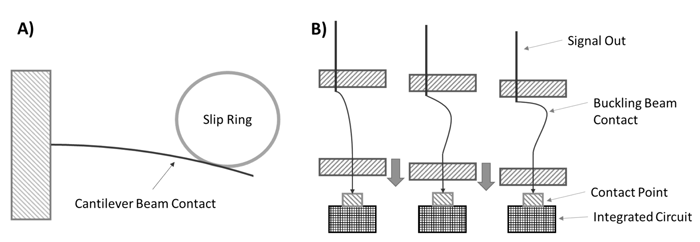
Figure 1: Example of cantilever beam contact on a slip ring and a buckling beam contact² on an integrated circuit.
These two designs operate under different mechanical regimes. Cantilever beams function under beam bending, with forces and stresses easily predicted by known equations. In contrast, buckling beams use empirical relationships to predict the onset of elastic buckling deformation.
Cantilever beam contacts have a load that is linearly dependent on deflection compared with buckling beam contacts that rapidly load to a critical value where they buckle followed by a period where the load changes very little with subsequent deflection as demonstrated in Figure 2.
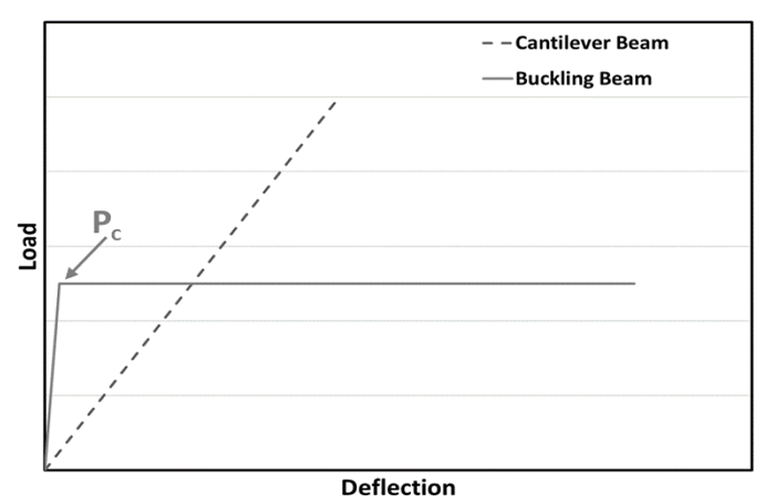
Figure 2: Schematic load vs deflection to failure comparison of cantilever vs buckling beam contacts.
The loading rate of a simple cantilever contact or the critical load value for a buckling beam contact are defined by equations 1 and 2, respectively, with key dimensions identified in Figure 3. Details on the loading rates of more complex cantilever beam contacts can be found in the Ney Contact Manual¹.
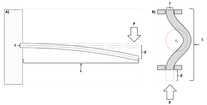
Figure 3: Schematic of cantilever bending and buckling load-deflection relationships.
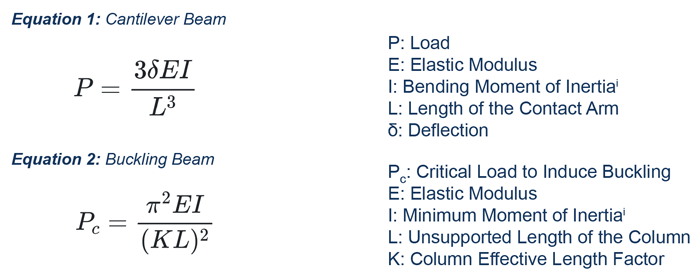
These formulas give designers a large amount of freedom in the contact design, as the load can be modified by changes to the length or cross section of the material. Changes to elastic modulus also influence the load, however elastic modulus is primarily driven by material composition. Changing the material has far-reaching consequences to electrical and wear performance; it is advisable to first evaluate changes to the contact geometry. The major difference or advantage to the cantilever beam is that its load is proportional to deflection, allowing for final tuning of the load by adjusting the total deflection of the beam.
Buckling beam probes are heavily affected by the Column Effective Length Factor, which is an empirical value controlled by the end constraints on the probe, these factors commonly range from 0.5 to 2.0³.
A designer can manipulate these end constraints to significantly change the load for otherwise nearly identical buckling beam probes.
The maximum possible deflection in a cantilever beam can be determined from equation 3. In buckling beam contacts, maximum deflection will be design–dependent, so there is no simple equation to solve for the maximum deflection. As deflection increases, the radius of the buckle will get steadily sharper, until it reaches a critical value where the maximum fiber stress in the buckling beam exceeds the material yield stress. The critical radius (rc) can be determined by equation 4.

The load-deflection characteristics of contact arms as well as the maximum possible deflection is a key to successful contact design. In order to learn more about the relationship between load and contact resistance please consult the Ney Contact Manual¹.
References:
1. Pitney KE. General Contact Theory. In: Ney Contact Manual: Electrical Contacts for Low Energy Uses. Bloomfield, Connecticut: The J. M. Ney Company; 1973. p. 100‒116.
(Download the Ney Contact Manual Here)
2. Benedetto, William E., and Joseph M. Moran. “Apparatus having a buckling beam probe assembly.” U.S. Patent No. 4,901,013. 13 Feb. 1990.
3. “Column Buckling ” MechaniCalc, Inc. https://mechanicalc.com/reference/column-buckling Accessed 7/8/2021
i Equations for moments of inertia of various beam cross sections can be found in reference 1.