Issue 044, Sept 15, 2022
Grant Justice, Sr. Research Metallurgist
This article will discuss what, at first, appears to be a basic concept: the difference between a switch and a connector, and the implications of these differences on design and material selection. Switches are devices that are designed to repeatedly close completing an electrical circuit and open breaking and isolating an electrical circuit. Connectors are semi-permanent devices that are part of a circuit but can be removed and replaced when the circuit is off. Figure 1 shows a basic illustration of a solenoid relay, the core function of a relay is as a switch frequently using silver-based materials as the contact point for the switch, but additionally all relays incorporate many connectors to wire them into the larger circuit.
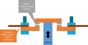
Figure 1: Simplified view of a relay showing the bolted connections for input and output and the arc resistance silver tin oxide contacts used for active switching.
The first major difference between switches and connectors are the number of times they are used. Many switches are rated for operation lifetimes in the millions or tens of millions of cycles.¹ Switches generally use lower contact loads to reduce component fatigue and reduced sliding contact, or wipe, to reduce wear. In order to maintain low contact resistance under low load/low wipe conditions, oxidation-resistant materials like silver-or noble-based alloys are utilized for the contact surface. This can be compared to a frequently used connector, such as a USB port, that is rated for 1,500 to 10,000 cycles of operation.² This 1,000x variation in operational cycles necessitates different design choices to avoid wear and fatigue failures. Connectors, due to lower operational cycles, can tolerate higher contact forces and larger wipes as both are effective at disrupting resistive oxide layers. This allows for lower cost materials like— copper, nickel, and tin—to be frequently employed.
The second major difference is that switches must complete and break live circuits and resist damage from any arcing or welding during operation. This frequently necessitates the use of expensive composite materials like silver – tin oxide, silver – cadmium oxide, and silver – tungsten for the contact of the switch.³ Connectors are almost exclusively designed to operate in non-arcing conditions, either when the circuit is off (i.e. the connection is made “cold”), or when the voltage or current are low enough
to minimize arcing concerns.
Connectors, in particular, are at risk of fretting failures. During normal operation, vibration or thermal expansion can cause small (<~125 μm) movements in the connection interface. These movements can cause abrasive wear generating small particles of metal oxide on the contact surface. These oxide particles are non-conductive and can slowly build up until they force the connecter to separate and break the circuit as described in Figure 2. This mechanism is called fretting.⁴ Switches are also potentially subject to this failure mode, however usually the gross mechanical action (>125 μm) of opening and closing the switch helps to clear the debris preventing an excessive buildup. Fretting failures can also be prevented by using noble metal connectors or coatings. Fretting wear can still potentially abrade a noble metal connector; however, noble metal particles usually remain conductive and do not break the circuit. Fretting failures are one of the reasons why circuits can sometimes be fixed merely by unplugging and
re-plugging any connectors in the circuit while it is deenergized and safe to do so.
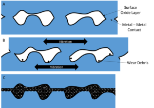
Figure 2: Schematic diagram of a fretting failure in a connector. A) two metal surfaces are pressed together and the oxide layer is punctured resulting in metal – metal contact and electrical conduction at 3 points; B) small amounts of vibrational sliding occur generating small particles of resistive metal oxide wear debris; C) buildup of wear debris forces both metal surfaces apart and the circuit is broken.
Deringer-Ney has decades of experience in the design and manufacture of high reliability connectors, contacts, and sliding contacts utilizing a wide range of precious and semi-precious materials in low to high power applications.
References:
- OMRON, “G6RL PCB Power Relay”, https://omronfs.omron.com/en_US/ecb/products/pdf/en-g6rl.pdf
- USB Implementers Forum, Inc, (2022) “USB Type-C® Cable and Connector Specification Release 2.1” Retrieved from https://www.usb.org/document-library/usb-type-cr-cable-and-connector-specificationrelease-21
- G. Justice, Tech Brief 037 – Arcing Contact Materials Selection, 2022. https://deringerney.com/arcingcontact-materials-selection/
- Braunovic, M “Power Connectors – Fretting” Electrical Contacts: Principles and Applications, edited by Slade, Paul G. CRC press, 2017.pp. 267-287