Grant Justice | Research and Development Manager
I. Introduction
This guide aims to identify the key performance aspects of arcing contact materials and their importance to medium voltage arcing contacts. Subsequently, the guide will support the initial selection and tradeoffs of silver-refractory contact material grades.
Arcing contacts are components of switching devices designed to handle the extreme conditions that occur when opening or closing electrical circuits under load. When an energized electrical circuit is interrupted, an electrical arc forms between the separating contacts. This arc is essentially a plasma channel of ionized gas that can reach temperatures of several thousand kelvin. As the circuit voltage increases, these arcs become more powerful and destructive. Arcing contacts serve as semi-sacrificial elements that bear most of this thermal and electrical stress, thereby protecting the main current-carrying components, such as copper busses, from damage. They are specifically engineered to withstand repeated arc formation, maintain circuit integrity, and safely extinguish arcs during operation. These components may be found in critical infrastructure equipment such as overload protection systems or circuit breakers, load-break switches, voltage regulating tap changers, and elsewhere in electrical utility infrastructure.
The reader should be aware that material selection for an arcing electrical contact is notoriously difficult as material, manufacturing method, and overall switch design all play a critical role in the final performance of the switch. The ASTM Subcommittee B02.05 on Precious Metals and Electrical Contact Materials and Test Methods states this clearly in the introduction to the ASTM B844 standard:
“The methods for manufacture (proprietary or otherwise) of these materials vary significantly among suppliers, and these methods influence such properties as arc erosion, contact resistance, and tendency to weld in service. Since the performance of contacts in a device depends on numerous factors outside the contact itself (opening speed, closing speed, contact pressure, contact bounce, environmental variations, assembly technique and variations, etc.) this guide cannot ensure performance control in the application. As part of the qualification on initial samples it is recommended that the user electrically test the materials in a functional manner for all devices applicable to the material’s use.”1
Particular attention will be paid in this guide to the contact quality, which is producer-dependent and a direct result of the manufacturer’s selection of raw materials and fabrication processes.
II. General Performance Trends of Arcing Contact Materials
Medium Voltage is defined as 1 kV to 100 kV and 1 kV to 69 kV nominal system voltages by ANSI C84.1 and IEEE Std 141, respectively.2,3 Applying this definition to the general contact material selection diagram in Figure 1 indicates that the contact tips will primarily be silver-refractory tips, including silver-tungsten (Ag-W), silver-tungsten carbide (Ag-WC), and silver-graphite (Ag-C) with a smaller fraction of applications potentially being serviced by silver-metal oxide refractory tips such as silver-tin oxide (Ag-SnO2) and silver-cadmium oxide (Ag-CdO). This would also include copper-tungsten (Cu-W) that can be considered to have analogous performance to silver-tungsten contacts if they are used in a protective environment, such as devices filled with oil, inert gases, or reducing gases.
Applications above a few thousand volts are primarily served by vacuum breakers and are considered outside the scope of this work.
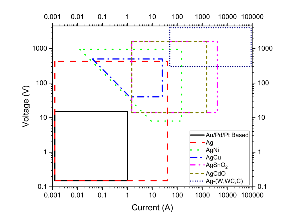
Figure 1: Basic contact materials selection chart based on application voltage and current.4, 5
At high currents and voltages, the performance requirements of the contact materials during opening and closing operations can be directly opposed to the performance requirements while the switch is closed. A review of the relative performance of all the arcing contact materials in Table 1 reveals that the Ag-W and Ag-WC contact materials occupy the extremes of the performance matrix; they are the most weld- and arc erosion-resistant materials, but also exhibit the highest contact resistance and cost. The designer should be cognizant of the relative tradeoffs and, as indicated in the introduction, verify through testing that the contact material pair in the particular use environment yields acceptable results.
Table 1: Relative performance of arcing contact materials for different elements of switching operation5
| ← Critical | Non-critical → | ||||||
| Material Performance | Arc Erosion Resistance | Weld Resistance on Make | Contact Resistance After Arcing | Weld Resistance of Closed Contacts | Arc Dwell Time | Reignition Voltage | Relative Cost |
| ↑ Superior | Ag-W, Ag-WC | Ag-W, Ag-WC | Ag | Ag-C | Ag-Cu, Pure Ag | Ag-SnO2, Ag-CdO | Ag, Ag-Cu, Ag-Ni (FG) |
| Ag-SnO2, Ag-CdO | Ag-C | Ag-C | Ag-Cu, Pure Ag | Ag-Ni | Ag-Ni | Ag-SnO2, Ag-CdO, Ag-Ni (PM) | |
| Ag-Ni | Ag-SnO2, Ag-CdO | Ag-Cu | Ag-SnO2, Ag-CdO | Ag-SnO2, Ag-CdO | Ag | Ag-C | |
| Ag-C | Ag-Ni | Ag-Ni | Ag-Ni | Ag-C Ag-W, Ag-WC | Ag-Cu | Ag-W, Ag-WC | |
| Ag-Cu | Ag-Cu, Pure Ag | Ag-SnO2, Ag-CdO | Ag-W, Ag-WC | Ag-C | |||
| ↓ Inferior | Pure Ag | Ag-W, Ag-WC | Ag-W, Ag-WC |
Arc Erosion Resistance is the most critical feature of a medium voltage arcing contact. The electrical arcs formed have temperatures measuring in the thousands to tens of thousands of degrees depending on the length, current, and arc type.5 This temperature is sufficient to melt and vaporize the surface of any contact material eroding the face of the contact. The rapid heating during arcing also causes high levels of thermal shock that can cause cracks to form, propagate, and eventually result in spalling of pieces of the contact during arcing. The extreme temperatures are best counteracted by the addition of refractory additions like tungsten or tungsten carbide that have very high melting and vaporization temperatures to slow arc erosion rates. Use of these refractory additions comes with tradeoffs: their use results in a decrease in fracture toughness and, thus, a greater tendency to spall. This tradeoff must be assessed for each application to determine optimum refractory loading.
Weld Resistance on Make of the contact pair is inversely proportional to the force required to re-open the switch after being closed. A high susceptibility to welding of the contacts can result in the situation that the switch mechanics cannot supply sufficient peak opening force, resulting in the switch failing closed. Medium voltage contacts form an arc during closing, thereby partially melting the surface prior to making final contact. The sequence of events produces an effect similar to percussive welding. Additionally, as the switch rebounds from the closing motion (“switch bounce”), the contact force is temporarily reduced by increasing the contact resistance. The associated restive heating leads to localized melting of the surface. The degree of welding on make is heavily influenced by switch design; any design improvements that reduce the duration of closing arcs or the occurrence of switch bounce will reduce welding on make.5 Switch performance can be bolstered with materials designed to reduce weld strength, which are more easily fractured during subsequent opening operations. Medium voltage contact materials use a refractory second phase to weaken the weld, typically either a refractory metal (e.g., Ag-W) or a metal oxide (e.g., Ag-SnO2).
Contact Resistance After Arcing is the steady state resistance once the contacts are past the initial wear-in period; this is typically higher than the initial contact resistance of undamaged contacts.5,6 Contact resistance should minimized to simultaneously reduce resistive loss of the circuit, resistive heating of the contact, and welding due to localized melting. This is accomplished by both achieving the maximum area of intimate clean metal contact between the two sides of the switch and reducing the contribution of interposing films and/or particles.7 For a given contact force, silver—and other noble metals—will have the lowest contact resistance of the materials from Table 1. This is due to silver’s low hardness producing a large contact area and silver’s inherent resistance to oxidation. In contrast, silver-tungsten contacts possess increased hardness from the tungsten phase, resulting in a lower contact area and greater constriction resistance compared to fine silver, combined with the propensity to form resistive oxides and silver tungstate5,6 on the surface, adding film resistance further increasing the contact resistance versus fine silver.
Welding of Closed Contacts occurs due to localized heating and melting of the asperities of a closed and energized contact.5,7 While generally a lower-priority consideration than the welding of contacts on make, this may occur if voltage drop across the contact pair exceeds the melting voltage (~370 mV for silver7). If this criterion is met, then asperities will soften, melt, and collapse until a sufficient contact area is achieved to reduce the local resistive heating, and subsequently cool and re-solidify the contact area. This occurs very quickly when the contact is first energized or during transient spikes in the power (i.e., inrush loading of motors, electrical short circuits, etc.). This melting is transient and limited to the contact interface; it will not result in an appreciable bulk heating of the contact. Materials with low contact resistance will experience the least melting of asperities resulting in smaller welds that are easier to fracture when the contacts are opened.
Arc Dwell Time is the amount of time the arc root will dwell at a specific location on the contact before it starts to move under the influence of Lorentz force caused by the arc.5 In order to for the arc root to move, the arc must create new charge carrier production sites on the contacts; this is accomplished by localized heating from the plasma jet as the arc deflects. Dwell time can range from fractions of a millisecond—0.2 ms to 0.5 ms depending on material for 4kA circuit breakers—to several miliseconds.5,8,9 This behavior is critical for breaking applications where it is desirable to move the arc off the initiation point to prevent excessive erosion of a single point of the contact. The dwell time is also strongly influenced by mechanical switch design, atmosphere inside the switch, and the presence or absence of an applied magnetic field. Its contribution to contact life, however, is significant as it directly correlates to the volume of material erosion during each switch cycle.
Reignition Voltage is the amount of voltage required to reignite a recently extinguished arc. This applies only while the contacts faces are still at elevated temperature due to the recent arcing. This is also referred to as the restrike voltage or instantaneous recovery voltage. This primarily applies to switches designed to break alternating current circuits where the arc is extinguished twice each cycle of the supply power, but remains at risk of re-striking as the voltage magnitude increases on the next half-cycle. If the supply voltage is below the reignition voltage, then the arc will not reignite. However, if the applied potential is above the reignition voltage, then arcs may continue to reignite until other factors, primarily contact separation, are able to prevent reignition.5 For medium voltage applications, the supply voltage can be considered to always be above the restrike threshold. Each arc re-ignition adds to the total arc dwell time, and thus increases erosion of the contacts.
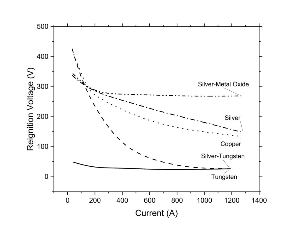
Figure 2: Restrike voltage of different contact materials as a function of the arc current.5
Relative Cost is always a consideration. The cost of contact tips is a mixture of processing costs and intrinsic (raw material) costs. As reviewed in Table 1, pure silver, silver-copper, and fine-grained (FG) silver-nickel alloys are possible to cast and process to the final desired shape using high volume production methods, resulting in contacts with a relatively low cost of manufacturing. Multiphase silver-nickel, silver-graphite, and silver-tin oxide are most frequently produced though higher cost extrusion processes using powder metal precursors. However, once extruded, they can be wrought processed into a final shape. Silver-refractory contacts cannot be cast, nor worked, and therefore must be made near-net-shape processing via powder metallurgy (PM) techniques (i.e., press-sinter, press-sinter-infiltrate, etc.) that tend to have the highest attendant production costs per contact.
III. Guidance on Medium Voltage Contact Material Selection
In the process of switch design, the engineer is typically tasked with selection of optimal grades and pairings of contact materials. As evidenced by the foregoing discussion, the designer must bear in mind that performance of the material cannot be treated independently from performance of the mechanical switch; this limits the specificity of guidance that can be provided in this manual. It is imperative to use this guide in conjunction with experimental device testing to ensure the optimal material selection is made.
A general ranking of considerations in medium voltage contact material selection can be found in Table 2:
Table 2: Ranking of medium voltage contact material selection considerations.
| Ranking | Design Choice | Examples |
| Most Important | Contact Material | Alloy Silver-Metal Oxide Silver-Refractory |
| Contact Quality | Porosity Dispersion of Second Phase Specified Supplier | |
| Refractory Phase | Tungsten Tungsten Carbide Graphite | |
| Contact Details | Volume Fraction of Second Phase Size of Second Phase | |
| Least Important | Contact Pair Asymmetry | Identical Materials Different Materials |
Contact Material considerations have largely been discussed above. The consequences of increases in contact resistance, arc dwell time, tendency of closed contacts to weld, decreased reignition voltage, and increased cost when using silver-refractory contacts tend to be high; it is recommended to use silver-metal oxide contacts if at all possible. However, in most medium voltage applications the erosion rate of silver metal oxide contacts renders them unsuitable, necessitating the use of silver-refractory contacts.
Contact Quality is likely the factor that will cause the most variation in the performance of the switch, and is simultaneously difficult to fully define. Comparisons between contacts produced by similar processes have been demonstrated to produce different performance.5,10 Unfortunately, the most easily tested metallurgical factors such as hardness, bulk density, or bulk conductivity are not predictive of erosion rate or overall contact performance.5 Destructive testing for metallurgical cross-section analysis is the best way to make a qualitative determination of contact quality. The desirable attributes are:
- Minimal contact porosity (i.e., no shrinkage voids or trapped gas).
- Uniform dispersion of the refractory in the silver matrix (i.e., no macroscopic gradation of refractory level across the entirety of the contact such as tungsten sinking during infiltration).
- Lack of silver ‘lakes’ or refractory agglomerate (i.e., microscopic areas with extremely high fractions of silver or tungsten).
- Low contiguity of the refractory particles (i.e., minimizing large, continuous chains of tungsten or tungsten carbide particles that could serve as preferential crack propagation pathways; however, some level of contiguity is necessary to prevent the tungsten from sinking during infiltration).
Examples of some of these undesirable microstructural features can be found in Figure 3.
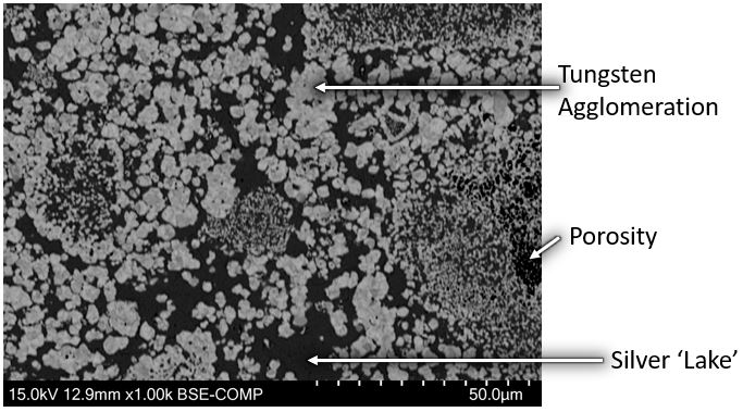
Figure 3: Example of undesirable silver-tungsten contact microstructure including porosity, tungsten agglomeration, and silver-rich regions (“lakes”)
Silver-refractory contacts are made by a wide variety of methods with concomitant variation in production cost and resulting contact quality. Commercial off-the-shelf circuit breakers, which require the use of silver-tungsten to pass Underwriters Laboratories’ short circuit testing, tend to use a price-optimized grade of silver-tungsten. This grade of material typically contains agglomerations of tungsten, residual porosity, and high levels of contiguity between the tungsten particles. These features are ultimately acceptable for circuit breaker application, but would have significant negative impacts on the performance of the contact material in more demanding medium-voltage contacting applications. A comparison between an off-the-shelf silver-tungsten contact in a circuit breaker and a “premium” silver-tungsten contact suited for demanding grid, industrial, and/or mobility switching applications can be found below in Figure 4.
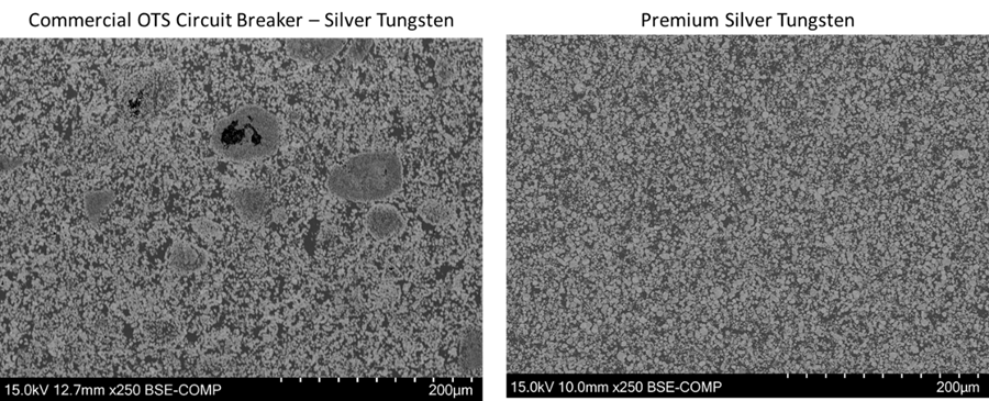
Figure 4: Comparison of an economy Ag-W contact from an off-the-shelf (OTS) circuit breaker rated for 240 volt alternating current (AC) at 20 A (left) vs a “premium” silver tungsten contact (right).
Refractory Phase effects can be difficult to assess due to their entanglement with manufacturing method and overall contact quality. The overall result is that the refractory phase may be considered of lower significance than to material quality. One study comparing similar contacts found that arc erosion rates varied by less than 7% between Ag-W, Ag-WC, and Ag-Mo tips when using similar volume fractions of refractory under the same test condition.11 There can, however, be some subtle differences between these refractory materials:
- Tungsten additions are the most common in silver-refractory contacts. The formation of complex oxides on the surface after arcing in air can give rise to higher contact resistance. The tungsten addition is slightly more ductile and tougher compared to tungsten carbide, potentially resulting in a greater resistance to spalling in some situations.
- Tungsten carbide additions react with air during arcing to produce some carbon monoxide gas that protects the contact surface from oxidation, thereby producing a lower and more stable contact resistance. Tungsten carbide-containing contacts have been reported to have a greater tendency to weld during high current short circuits compared to tungsten-containing variants.12 Generally, these contacts will be slightly harder compared to silver tungsten. The lower fracture toughness of the reinforcement phase can lead to slightly higher arc erosion due to increased spalling during arcing.
- Molybdenum is a much rarer (and, perhaps, underutilized) addition versus tungsten or tungsten carbide. Its oxide is less stable compared to tungsten’s, so it tends to have slightly lower contact resistance compared to tungsten.12 Molybdenum is also softer than tungsten, resulting in a lower hardness which also improves contact resistance and resistance to spalling.5 Molybdenum has a lower melting point compared to tungsten or tungsten carbide, which results in a higher levels of arc erosion due to melting and expulsion.
- Graphite additions do not add a high level of arc erosion resistance, but produce a very high level of weld resistance both on make and for closed contacts.5 Silver-graphite is very rarely used on both sides of a medium voltage contact pair, but it is occasionally viable for use as one-half of the contact pair if erosion is concentrated preferentially to a single tip.
- Hybrid contacts may contain combinations of the reinforcements above. In some cases, graphite and refractory additions (e.g., silver-tungsten-graphite) are used in an effort to combine the low-weld performance of silver-graphite with the arc erosion resistance of silver-tungsten. However, it is usually observed that the graphite additions result in a rapid increase in arc erosion, making these materials less common.13 Other hybrid contacts are made using both tungsten and tungsten carbide to provide some of the benefits of both reinforcements.
Volume Fraction and Size of Second Phase is significant in balancing the melting and expulsion of the silver phase and brittle fracture and spalling due to high refractory additions. Contacts that are exposed to higher-current or longer-duration arcs benefit from greater loading of the refractory phase to handle the demanding arcing load. This is illustrated well in Figure 5, where 366 amp testing demonstrates better performance at about 40wt.% tungsten, while 7,278 amp testing has the optimal performance at closer to 70 wt.% tungsten. It should be noted that the effect of loading optimization tends to be small; for instance, if a 70 wt.% tungsten contact was used instead of a 40 wt.% tungsten contact at 366 A, the erosion rate would increase by 27% based on this data set, suggesting that the lower loading could be used successfully.
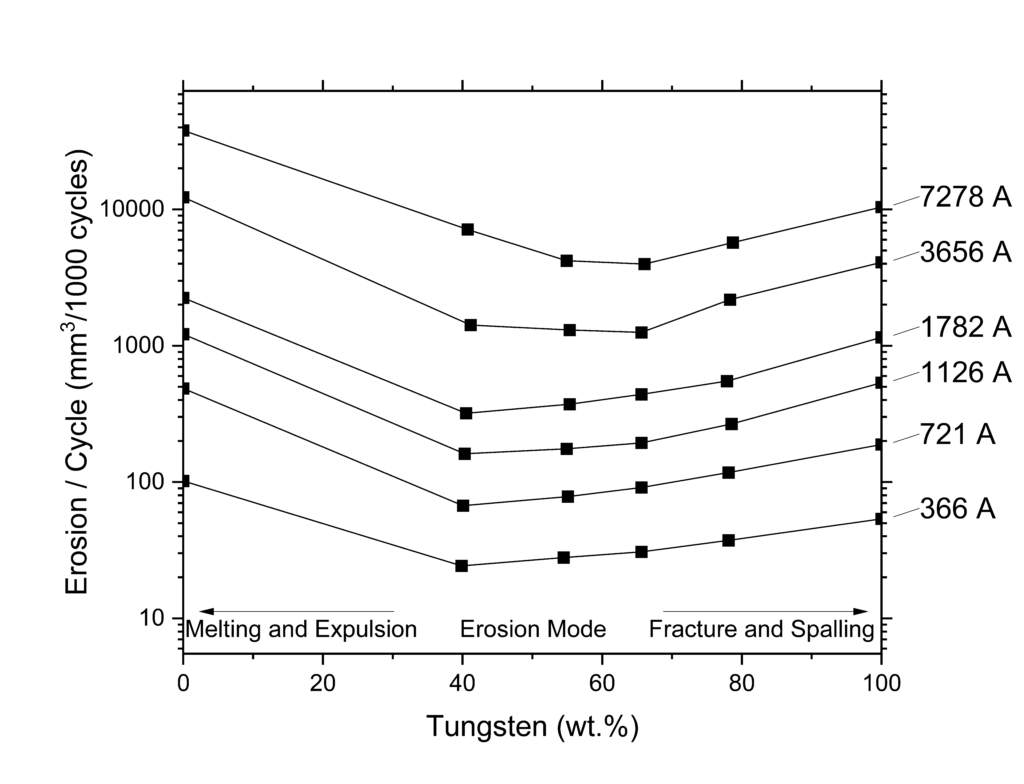
Figure 5: Arc erosion rates of copper-tungsten in oil from 366 to 7,278 amps.5,14
Similar behavior to higher refractory loading can be achieved by using finer refractory particles. A higher number-density of refractory particles due to reduced particle size may result in an increased tendency to form nonuniform microstructures with greater refractory contiguity thus locally lowering the material fracture toughness. General trends associated with particle loading and size can be found in Table 3:
Table 3: Trends in performance due to particle size and loading. 5,6
| Arc Erosion Due to Melting | Arc Erosion due to Spalling | Contact Resistance | Hardness | |
| Increasing Particle Loading | Decreases | Increases | Increases | Increases |
| Increasing Particle Size | No data found | Decreases | Decreases | Decreases |
Contact Pair Asymmetry refers to the use of two different contact materials in the switch. In direct current (DC) and some AC applications arc erosion will be biased toward one of the contacts based on a combination of factors such as gap, voltage, current, and opening speed. If one of the contacts has been found to have a much higher rate of arc erosion, it will lead to a reduced lifetime projection for the switch assembly. Erosion can be equalized by substituting a different material to tune the performance of the system. A common example would be pairing a silver-tungsten contact (high erosion side) with a silver-graphite contact (low erosion side). The addition of the silver graphite contact can significantly decrease the contact resistance of the closed contacts and increase the weld resistance of the closed contacts versus a switch that uses silver tungsten on both sides. It should be noted that silver-refractory contacts are not frequently paired with silver-metal oxide contacts.
IV. Summary
Medium voltage contact material selection is multifaceted and fraught with tradeoffs due to the extreme environment in which the devices operate. For some applications, silver-tin oxide may still be used; however, elevated levels of erosion or welding necessitate the use of silver-refractory contacts. Care should be taken to identify a high-quality manufacturer to ensure the contacts will perform well, and performance should be judged through real-life application testing. Relative to the contact material family and manufacturer selection, the choice of reinforcement phase is less critical. Further optimization of the refractory volume fraction, and particle size can produce modest gains in performance, but these incremental improvements can only be realized in a well-designed switch. If the application experiences asymmetry of arc erosion, then design flexibility can be exercised in replacing the low-erosion contact with an alternative to reduce the contact resistance and/or weld force.
V. References
- ASTM Standard B844-98, 2016, “Standard Guide for Silver-Tin Oxide Contact Material” ASTM International, West Conshohocken, PA, 2016, DOI: 10.1520/B0844-98R16, www.astm.org.
- “IEEE Recommended Practice for Electric Power Distribution for Industrial Plants,” in IEEE Std 141-1993, 29 April 1994, doi: 10.1109/IEEESTD.1994.121642.
- “Electric Power Systems and Equipment – Voltage Ratings (60 Hz),” ANSI C84.1-2020 10 March 2020, ANSI.
- McBride, J 2021, 4 Day Intensive Course on Electrical Contacts – Switching Contacts, lecture notes, Holm Conference, 23 Oct. 2021.
- Slade, Paul. Electrical Contacts Principles and Applications. CRC Press, 2014.
- Ray, Nachiketa, et al. “Effect of WC particle size and Ag volume fraction on electrical contact resistance and thermal conductivity of Ag–WC contact materials.” Materials & Design 85 (2015): 412-422.
- Pitney, Kenneth E. Ney Contact Manual: Electrical Contacts for Low Energy Uses. Revised 1st Edition. Bloomfield, Connecticut: Deringer-Ney Inc., 2022.
- Li, Wangpei, et al. “Effect of Cu content on the electrical erosion of tungsten copper contacts switching load-current in vacuum.” Proceedings of the Forty-Eighth IEEE Holm Conference on Electrical Contacts. IEEE, 2002.
- Behrens, Nordholm. Lichtbogenwanderung in leitungsschutzschaltern. na, 1980.
- Walczuk, E. “Investigations of technical properties of Ag/W contact materials for the moulded case circuit breaker.” Proc. ICEC, Berlin, 1982 (1982): 180-188.
- Leung, Chi-Hung, and Han Kim. “A comparison of Ag/W, Ag/WC, and Ag/Mo electrical contacts.” IEEE transactions on components, hybrids, and manufacturing technology 7.1 (1984): 69-75.
- Vinaricky, Eduard & Horn, Guenther & Behrens, Volker. Data Book of Electrical Contacts. DODUCO GmBH, 2010.
- Leung, Chi, et al. “Electrical and mechanical lives of Ag/C and Ag/WC/C Contacts.” 26th International Conference on Electrical Contacts (ICEC 2012). Stevenage UK: IET, 2012.
- Zessack, I. “Burn-up Behaviour of Sintered Contact Materials Tested Repetitively at Currents Ranging from 400A to 7000A in Oil.” Proc. of 9th Intr. Conf. on Elect. Contact Phenom.. 1978.