Deringer-Ney Research & Development Department
January 2025
I. Introduction
Brazing is a complex and nuanced field that the American Welding Society (AWS) takes over 700 pages to cover in their ‘Brazing Handbook’.1 This discussion will focus exclusively on brazing as it pertains to connecting medium voltage arcing contact tip materials to a copper body or bus bar, with the goal of assisting the reader in the selection of the optimum braze alloy.
It is useful to start with some definitions to help understand the specific scope of this topic:
- Medium Voltage is defined as 1 kV to 100 kV and 1 kV to 69 kV nominal system voltages by ANSI C84.1 and IEEE Std 141, respectively.2,3
- Brazing is considered to be the process of joining two metal pieces by introducing a third, dissimilar alloy. The third alloy should have a melting point above 450°C, but below the melting point of the pieces being joined. General guidance is contacts over 7 mm in diameter are best attached by brazing.⁴ Silver alloy brazing is sometimes colloquially referred to as “hard soldering” or “silver soldering.”
- Arcing Contact Materials used in medium-voltage applications can include Silver-Cadmium Oxide (Ag-CdO), Silver-Tin Oxide (Ag-SnO2), Silver-Tungsten (Ag-W), Silver-Tungsten Carbide (Ag-WC), and Copper-Tungsten (Cu-W).
II. Brazing Processes
Brazing tends to be the preferred method of attachment for medium voltage arcing contact tips. Many designs utilize a large contact area but comparatively low overall contact thicknesses. Stress resulting from arc damage can cause the contact edges to try and peel away from the base metal, so bonding that extends to the contact edges is critical.⁴ These factors, coupled with relatively low material strengths of the arcing contact materials, results in a need to achieve uniform bonding so that the contact is mechanically supported. This is best accomplished by flowing a filler metal—a braze alloy or solder alloy—into the joint. Most solder alloys based on lead or tin are not thermally stable enough to survive the elevated temperatures experienced in medium voltage applications, so braze alloys become the preferred solution.
This guide will primarily focus on continuous furnace brazing. In this process, a pre-cut foil of braze material is fixtured between the base metal and the contact. Then, the assembly is passed through a furnace on a conveyer belt under a hydrogen containing atmosphere, typically with either 75% or 100% hydrogen by volume. The reducing hydrogen atmosphere will scavenge oxygen from the surface of the copper and the contact, providing a nascent metal surface for the braze to wet. Blistering due to the reduction of oxides just under the base metal surface can occur in this process due to hydrogen diffusion, typically necessitating the use of oxygen-free copper grades. The use of hydrogen obviates the use of chemical fluxes and later flux-cleaning steps.
Table 1: Summary of joining methods and their respective strengths and weaknesses in medium voltage applications.
| Joining Method | Strengths | Weaknesses |
| Brazing | – Large coverage area underneath the contact – Continuous brazing operation is possible – Reducing atmosphere can be used to clean workpieces | – High capital and utility costs – Fully anneals workpieces – Susceptible to surface contamination affecting wetting |
| Laser welding | – Can fully constrain contact perimeter to prevent contact “peeling” – A third intermediary material is not required | – Single-piece operation and high cycle time – Does not constrain the center of the contact – Refractory or oxide phases in the contacts can lower weld strength |
| Resistance welding | – Rapid assembly due to ease of automation – Low cost of capital equipment Ability to acquire high quality process feedback data | – Small coverage area under the contact – Additional welds per workpiece must overcome current shunting – Resistance welding can be difficult on highly conductive materials – Refractory or oxide phases in the contacts can lower weld strength |
| Soldering | – Continuous reflow operation possible – Low cost of capital equipment | – Low thermal stability of the joint – Solder alloys have low strength Requires fluxes or similar cleaning agents |
| Ultrasonic welding | – A third intermediary material is not required – Large coverage area underneath the contact | – Single-piece operation and high cycle time – Tooling damages a surface of the workpiece |
III. Braze Alloy Selection Criteria
The performance requirements for the braze filler in this application differ significantly from many other metal joining applications. A short review of key considerations when selecting a braze alloy are ranked in Table 2. Processing temperature range, wetting, and reactivity of the alloy ranking as critical requirements, while porosity susceptibility, conductivity, and strength are less critical for joining medium voltage contacts.
Table 2: Ranking of Braze Alloy Behavior for Joining Medium Voltage Contacts
| Importance for Medium Voltage Contacts | Braze Alloy Behavior | Requirement |
| Critical | Process Temperature Range | Below silver-copper eutectic temperature |
| Critical | Wetting | Wets copper, silver, and any oxide or refractory phase present at the braze joint |
| Critical | Reactivity | Does not degrade any materials present at the braze joint |
| Moderate | Porosity | <30% Porosity with continuous perimeter bonding |
| Not Critical | Strength | Not critical provided porosity target is achieved |
| Not Critical | Conductivity | Not critical provided porosity target is achieved |
Process temperature range is likely the most critical of the brazing alloy behavior for medium voltage contacts. The copper of the base and the silver of the contact will begin to form a liquid if placed in direct contact at temperatures higher than 778°C for sufficient time. This can lead to runaway melting behavior as demonstrated in the cross-sections in Figure 1.The braze on the left has the desired appearance of a uniform joint, with a thin, evenly-wet layer of braze alloy between the silver backing of the contact tip and the copper base. The braze on the right in Figure 1 was performed at a higher temperature than ideal, thus melting of both the copper base and the silver contact into a very large zone that completely consumed the fine silver layer, and much of the copper base. The best way to avoid runaway melting is to select a braze alloy with a low melting point ideally well below the 778°C silver-copper eutectic temperature.
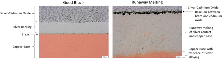
Figure 1: Comparison of cross-sections between a good braze (left) and a braze that experienced runaway melting (right). Scale bar is 200µm.
Wetting of the braze metals to contact tip and base metal is a key consideration. Silver and copper both have a high affinity for silver- or copper-based braze alloys due to their chemical similarity (“like wets like,” as the metallurgical saying goes). However, neither silver- and copper-based braze alloys readily wet oxides. Phases that inhibit braze wetting can include copper oxides (i.e., on an oxidized base metal), or oxides intentionally present in the contact (i.e., cadmium oxide or tin oxide). Neither silver nor copper wet tungsten or tungsten carbide well. Common mitigations for these issues may include the addition of nickel can improve tungsten / tungsten carbide wetting, and/or phosphorus to reduce copper oxides that may be present on the workpiece.⁵
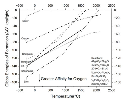
Figure 2: Partial Ellingham Diagram showing energies of formation for oxides of elements commonly found in medium voltage contact assemblies⁶
Reactivity is a key consideration, as many braze alloys may react with elements in the contact or base to produce undesirable results. The relative affinity of common elements for oxygen can be compared using an Ellingham Diagram found in Figure 2. In this visual tool, each line represents the driving force for the formation of oxide species at increasing temperature at a fixed partial pressure of oxygen. Those elements appearing lower on the diagram have a very high driving force for forming oxides; these strong oxide formers can potentially rob oxygen from elements positioned above them. For instance, a silver- cadmium oxide should not be in contact with metals that fall below cadmium on the Ellingham diagram. In this example, metallic zinc will react with cadmium oxide to produce zinc oxide and pure cadmium during brazing. This is undesirable, as the cadmium oxide phase is necessary for the proper performance of a silver-cadmium oxide arcing contact.
Braze porosity is more tolerable in electrical contacts compared to other braze applications. Due to the higher strength of the braze alloys versus the base material, the braze joint can contain significant areas of porosity and still meet the requirements for the application. However, the perimeter of the braze is important in arcing contacts, as repeated melting and solidification of the surface due to arc strikes tends to form a residual surface tensile stress. This creates a stress state that can lift or “peel” the contact off the base material. Porosity levels as high as 50% have been found not to diminish the lifetime of the contact, although braze joint porosity levels of no more than 20-30% are considered best practice.⁴
Strength is usually not a major requirement for joining medium voltage contacts to a copper base. The heat introduced via furnace brazing is sufficient to anneal the copper, and the highly alloyed braze material is typically stronger than the annealed copper base material. A comparison of braze joint strength data seen in Figure 3 indicates that, under ideal situations, the braze joint strength can be as high as four times the strength of the copper base metal. Even in non-optimal situations, such as excessively large braze joint thicknesses, the braze strength still exceeds that of the base metal.
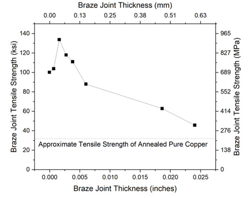
Figure 3: Historical relationship between braze joint thickness and resulting strength.⁸
Conductivity of the braze joint, somewhat counterintuitively, is not a major consideration in materials selection for medium voltage arcing applications. The contact resistance—the sum of constriction resistance, film tunneling resistance, and third-body resistances—of the closed contact pair is a much larger ohmic resistance than the braze joint. This is due to the high proportion of the interfacial area wetted by the braze alloy (70-80%, as discussed in the prior section), and low thickness of the braze joint⁷.
IV. Braze Alloy Compositions
This guide considers five major families of braze alloys:
- Aluminum and Magnesium braze alloys are primarily used for brazing aluminum and magnesium. These alloys are highly reactive due to their composition which creates additional challenges for brazing reducing their use with other alloy systems.
- Copper-based alloys see significant use in brazing and are used in a wide range of alloy systems. Composition and properties of select copper-phosphorus braze alloys can be found in Table 3.
- Silver-based alloys are also common braze alloys and see use in a wide range of systems. Composition and properties of select silver braze alloys can be found in Table 4.
- Gold-based alloys perform well but are very expensive and due to cost see less frequent use.
- Nickel-based alloys perform well but tend to have much higher melting points and are used in predominantly in high temperature applications.
Braze alloys are usually formulated to be near a eutectic composition to take advantage of lower melting temperatures found in certain metal alloy systems. In the case of copper-silver, the composition of 39 at.% Cu-61 at.% Ag (28 wt.% Cu-72 wt.% Ag) has a depressed melting point of 778°C; ~300°C lower than the melting point of pure copper and ~200°C lower than the melting point of pure silver, as seen in Figure 4. It should be noted that pure and low-alloy silver and copper in physical contact at or above 778°C will start to spontaneously form a eutectic alloy.
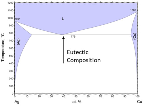
Figure 4: Phase diagram showing the eutectic reaction of Ag and Cu.10
Table 3: Nominal chemical composition (wt.%) and melting range of copper-phosphorus brazing filler metals1,9
| AWS Designation | Cu | Ag | P | Solidus [Start of Melting] °C | Liquidus [End of Melting] °C |
| BCuP-3 | Balance | 5 | 6 | 643 | 813 |
| BCuP-4 | Balance | 6 | 7 | 643 | 718 |
| BCuP-5 | Balance | 15 | 5 | 643 | 802 |
| BCuP-8 | Balance | 18 | 6 | 643 | 666 |
Table 4: Nominal chemical composition (wt.%) and melting range of cadmium-free silver brazing filler metals1,9
| AWS Designation | Ag | Cu | Zn | Ni | Sn | Solidus (Start of Melting) °C | Liquidus [End of Melting] °C |
| BAg-4 | 40 | 30 | 28 | 2 | 671 | 779 | |
| BAg-5 | 45 | 30 | 25 | 663 | 743 | ||
| BAg-6 | 50 | 34 | 16 | 688 | 774 | ||
| BAg-7 | 56 | 22 | 17 | 5 | 618 | 652 | |
| BAg-8 | 72 | 28 | 779 | 779 | |||
| BAg-9 | 65 | 20 | 15 | 671 | 718 | ||
| BAg-10 | 70 | 20 | 10 | 691 | 738 | ||
| BAg-13 | 54 | 40 | 5 | 1 | 718 | 857 | |
| BAg-13a | 56 | 42 | 2 | 771 | 893 | ||
| BAg-18 | 60 | 30 | 10 | 602 | 718 | ||
| BAg-20 | 30 | 38 | 32 | 677 | 766 | ||
| BAg-21 | 62 | 29 | 3 | 6 | 691 | 802 | |
| BAg-24 | 50 | 20 | 28 | 2 | 660 | 707 | |
| BAg-28 | 40 | 30 | 28 | 2 | 649 | 710 | |
| BAg-34 | 38 | 32 | 28 | 2 | 649 | 721 | |
| BAg-35 | 35 | 32 | 33 | 685 | 754 | ||
| BAg-36 | 45 | 27 | 25 | 3 | 646 | 677 | |
| BAg-37 | 25 | 40 | 33 | 2 | 688 | 779 |
A review of the various braze alloys shows that BAg-7, BCuP-8, and BAg-24 are among the most common furnace brazing alloys considered for medium voltage contact applications.
BAg-7 is a widely-used braze alloy. The low melting point promotes a wide and robust process window helping to maximize the likelihood of a high quality braze without the risk of runaway melting of the contact. The zinc is sufficiently reactive to potentially reduce both tin and cadmium oxides in the contact, so care should be taken to ensure the braze alloy does not contact the oxides.
BCuP-8 is also a widely-used braze alloy. The low melting point produces a robust process window, however this alloy is very fluid and tends to produce thinner joints.1 This is generally desirable, provided that the parts are sufficiently toleranced to produce a good mating fit prior to brazing. The phosphorus addition causes the braze alloy to be self-fluxing as the phosphorus will react with any copper oxides to produce P2O5 gas and a clean metal surface for the braze to interact with. However, if the gas is not able to effectively escape large braze joints, then this can lead to an increase in porosity due to retained gas. Similarly, there is some risk that the phosphorus can reduce cadmium oxides. However, tin oxides are generally stable enough to potentially resist reduction by phosphorus. This should not be used to braze silver-nickel contacts with nickel over 10% due to the potential formation of brittle nickel-phosphorus compounds.¹
BAg-24 may be considered for use with tungsten- or tungsten carbide-containing contacts. This is the lowest melting point of the nickel-containing braze alloys listed above. The nickel addition provides significant improvements in wetting behavior around tungsten potentially reducing braze joint porosity. However, the higher melting point of the alloy reduces the potential process window, and increases the risk of runaway melting of the contact.
V. Contact-Braze Material Interactions
Copper alloys are generally selected for high thermal and electrical conductivity, so C10000, C10100, and C11000 are common choices for contact subassembly components that are not directly exposed to arc strikes. A drawback is C11000 has a higher oxygen content. Entrained copper oxides can react with hydrogen to form pockets of water vapor leading to blistering, cracking, or embrittlement of the material. Care must be taken when selecting this alloy for use in furnace brazing as the hydrogen atmosphere can instigate degradation of C11000.1,4
Silver-Cadmium Oxide (Ag-CdO) is being phased out as a contact material due to its cadmium content, especially to meet European statutory and regulatory requirements. It does still have some situational performance advantages, so some legacy products are still present in North American markets. Cadmium oxide is vulnerable to reduction by hydrogen, zinc, tin, and/or phosphorus. When using BAg-7 or BCuP-8, it is imperative to keep the these brazes from contacting the contact material to avoid the undesirable effects shown in Figure 5. Contact manufactures commonly include a pure silver backing on the contacts to prevent direct interaction between the braze alloy and the contact.
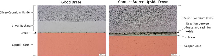
Figure 5: Comparison of cross-sections between a good braze (left) and a braze that occurred when the Silver-Cadmium Oxide contact was incorrectly assembled upside down allowing the braze alloy to react with the cadmium oxide (right). Scale bar is 200µm.
Silver-Tin Oxide (Ag-SnO2) is the primary replacement to silver-cadmium oxide, replacing the toxic cadmium oxide with relatively benign tin oxides. The tin oxide is slightly less likely to be reduced on contact with phosphorus than cadmium oxides, so BCuP-8 performs well for brazing Ag-SnO2 composites. The zinc in BAg-7 can potentially reduce the tin oxide if the contacts do not have a pure silver face. Since these are manufactured by similar processes to silver-cadmium oxide, it is standard to include a pure silver face so BAg-7 can typically be used without negative consequences.
Copper-Tungsten (Cu-W) and Silver-Tungsten (Ag-W) are both easier to braze vs the silver metal oxides, since they do not contain any specific metal oxides that have to be protected. However, tungsten is more difficult to wet, potentially creating wetting issues which are best addressed though the inclusion of nickel-containing braze alloy BAg-24.¹ In most cases, Ag-W and Cu-W contacts are etched to remove tungsten from the surface to promote more stable brazing allowing the use of both BAg-7 and BCuP-8. Copper-tungsten contacts specifically do not suffer from the potential risk of runaway melting since there is no source of silver outside of the braze alloy to generate the eutectic so a potentially broader range of braze alloys can be used. However, in practice, copper-tungsten contacts are frequently assembled at the same facilities as silver-tungsten contacts, so similar braze alloys are generally recommended for ease of production.
Silver-Tungsten Carbide (Ag-WC) is one of the more difficult composite materials to braze, as the tungsten carbide is difficult to wet for both silver and copper, especially at brazing temperatures. Ideally, a Ni addition would be used to facilitate brazing.⁵ These contacts are frequently etched to remove any surface tungsten carbide, although the chemically resistant nature of WC makes this a difficult operation. A braze alloy may also be added to the back of the contact during production to reduce the risk of subsequent brazing issues during assembly.
VI. Summary
BAg-7 and BCuP-8 are favored for furnace brazing of medium voltage electrical contacts. Care must be taken to ensure no negative reactions occur with tin or cadmium oxides, which is usually managed though the addition of a fine silver backing. When using tungsten or tungsten carbide containing contact tips, BAg-24 offers some potential advantages in wetting the tungsten or tungsten carbide due to its nickel content. Alternatively, tungsten may be removed from the surface by chemical etching to improve wetting of BAg-7 and BCuP-8. In summary, BAg-7 is recommended for most continuous furnace brazing applications where the hydrogen atmosphere is sufficient to reduce surface oxides from the contact tip and copper body.
VII. References
- American Welding Society (AWS). Brazing Handbook 5th Edition. AWS, 2011.
- “IEEE Recommended Practice for Electric Power Distribution for Industrial Plants,” in IEEE Std 141-1993, 29 April 1994, doi: 10.1109/IEEESTD.1994.121642.
- “Electric Power Systems and Equipment – Voltage Ratings (60 Hz),” ANSI C84.1-2020 10 March 2020, ANSI
- Slade, Paul. Electrical Contacts Principles and Applications. CRC Press, 2014.
- Ray, Nachiketa, et al. “Wetting and solidification of silver alloys in the presence of tungsten carbide.” Acta Materialia 144 (2018): 459-469.
- Howard, Stanley M. “Ellingham diagrams.” SD School of Mines and Technology 9 (2006).
- Pitney, Kenneth E. Ney Contact Manual: Electrical Contacts for Low Energy Uses. Revised 1st Edition. Bloomfield, Connecticut: Deringer-Ney Inc., 2022
- Ruiz, Mariana. “The Effect of Joint Clearance on Braze Joint Strength.” Lucas Milhaupt Blog, 2015, https://blog.lucasmilhaupt.com/en-us/about/blog/joint-clearance-and-joint-strength
- Silver Brazing Alloys. Prince and Izant. Retrieved December 4, 2024 from https://princeizant.com/metals/brazing-filler-metals/silver-alloys
- Cao W., Chang Y.A., Zhu J., Chen S., and Oates W.A., Ag-Cu Phase Diagram, ASM Alloy Phase Diagrams Database, P. Villars, editor-in-chief; H. Okamoto and K. Cenzual, section editors; http://www.asminternational.org, ASM International, Materials Park, OH, 2016.